Introduction to USRP Communications
Chapter 1
IQ Transmission
Table of Contents
1.1 Assemble the cRIO Hardware
1.2 Prepare the cRIO for FIRST USE
1.2.1 Automated Remote System Discovery Troubleshooting
1.2.2 Solve network issues with RIO
1.2.3 Software installation on RIO Hardware
1.2.4 Selecting program mode for c-series modules
1.3 Configuring the sbRIO based hardware
1.4 Recommended project architecture
NI CompactRIO is a small, rugged industrial control and acquisition system incorporating reconfigurable I/O (RIO) FPGA technology. The CompacRIO platform has the flexiblility to span a wide range of applications from field data logging with sophisticated analysis to high-performance nano-second control with small form factor. The CompactRIO system is the combination of Chassis (with controller) and I/O modules. The metal multi-slot reconfigurable chassis contains FPGA, Real-Time controller and slots for the I/O Modules. CompactRIO I/O modules communicates to and from any external devices, such as sensors and actutors.
- Assemble the cRIO system
- Prepare the cRIO for first use
- Recommended project architecture
- First FPGA project
1.1 Assemble the cRIO hardware
1. Connect the c-series modules to cRIO Chassis
(a) Note: Make sure that nothing is connected to the modules before inserting into the Chassis
2. Connect to PS-16 power supply DC output to the cRIO (DC + terminal of the power supply to V terminal and DC – terminal of the power supply to C terminal of cRIO) and ensure the wires are snugly in place.
3. Connect the cRIO to host computer using USB Cable.
4. Connect the PS-16 AC supply terminals to main socket and turn on the power supply.
We recommend to use USB connection to connect the cRIO to host computer to avoid the common networking problems. This USB connection is emulated as an Ethernet device. An automatic DHCP network is created over the USB device port, which allows for system updates apart from the physical Ethernet connection. The DHCP server assigns new target IP addresses from block 172.22.11.*. Once it’s powered on, the target will show in MAX under Devices and Interfaces and Remote Systems.
1.2 Prepare the cRIO for FIRST USE
1. Open NI MAX (Measurement & Automation Explorer) from the desktop or start menu.
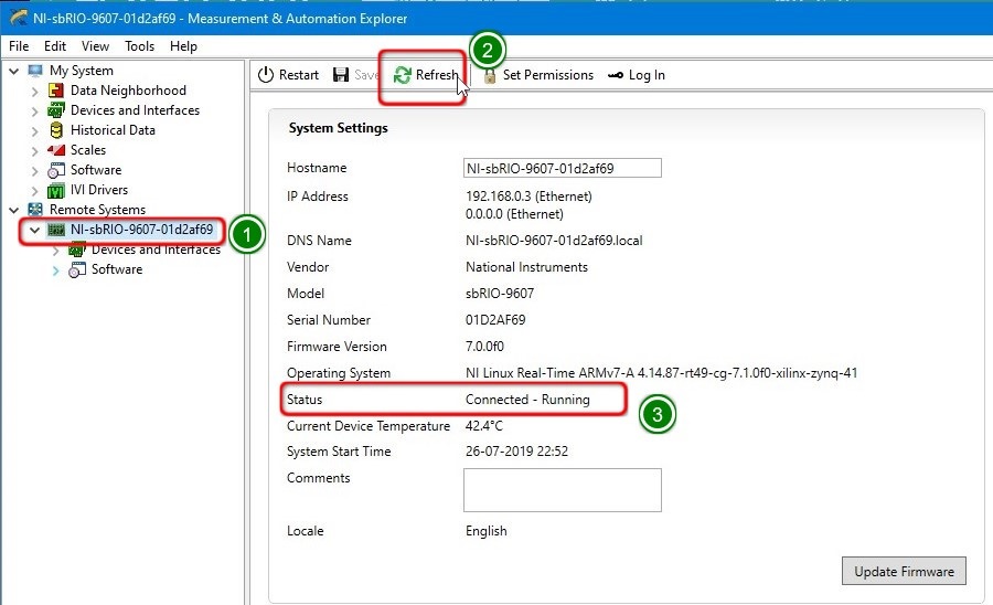
2. Expand Remote Systems and Select the cRIO Controller (1) Select System Settings (2) in the right-side panel and verify the CompactRIO controller by matching the model and serial number of your device (3).

1.2.1 Automated Remote System Discovery Troubleshooting
NI System Configuration 15.0 introduced a troubleshooting utility called Troubleshooting Remote System Discovery Wizard to assist with device discovery issues. This utility automates some of the troubleshooting process and generates a set of additional procedures tailored for your device and configuration. Complete the following steps to launch the utility .
1. Open NI MAX
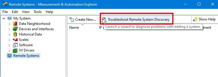
2. Select Remote Systems and Click on “Troubleshoot Remote System Discovery” button in right side panel.
3. Click the Type dropdown menu and select the type of your RIO hardware (1). Click the Model dropdown menu and select your RIO hardware model number (2). (in this example, we are using cRIO hardware architecture and the model number is 9054). Click Next button (3).

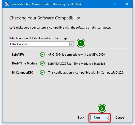
4. Select the required LabVIEW version (1). The utility will search & confirm the LabVIEW Version, Real-time Module & NI CompactRIO drivers compatibility with the RIO Hardware. Click Next button.
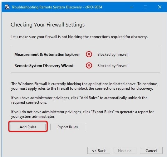
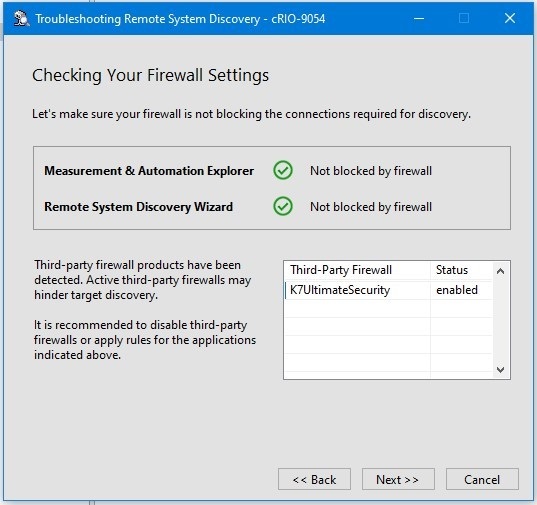
5. The utility will check for the NI MAX network access. If its blocked by firewall and you have administrator privilege, Click the Add Rules button. If you don’t have administrator privilege, contact the system administrator to provide the network access for NI MAX.
6. Now Measurement & Automation Explorer (NI MAX) and Remote System Discovery Wizard are having network access.
7. The wizard will display the list of RIO hardware available in the network. Select the cRIO 90XX (1) hardware and click the Next button (2)

8. Now cRIO hardware is available in NI MAX

1.2.2 Solve network issues with RIO
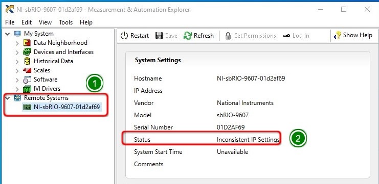
When NI MAX faces network problems while communicating between the host and target systems, it says “Inconsistent IP Settings”. Follow the below procedure to solve it.
1. Open NI MAX and Expand Remote Systems > NI RIO (sbRIO – 9607 is used in this example) (1). The status of the device is displayed as “Inconsistent IP Settings” (2).
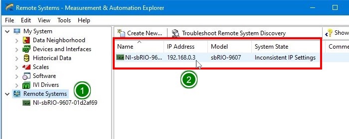
2. Click the Remote Systems (1) and identify the RIO hardware IP address (2).
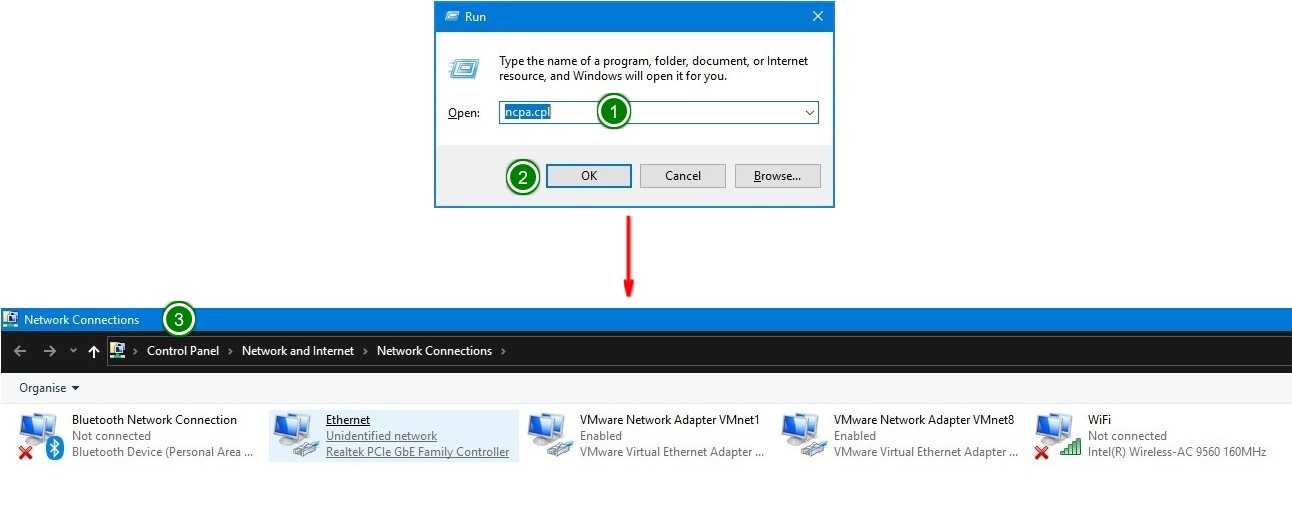
3. Press Win + R to open the Run box. Type ncpa.cpl (1) and click OK button (2) to open the network connection window (3).
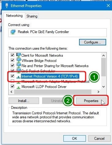
4. Right Click on the Ethernet adapter (1) and select Properties (2) to get the Ethernet adapter properties window (3).

5. Select Internet Protocol Version 4(TCP/IPv4) (1) and click Properties button (2).
6. Select Use the following IP address option and specify the static IP Address (1). Click OK button (2) to close the window.

7. Open NI MAX. Select Remote Systems > NI sbRIO 9XXX (1) and click the Refresh (2) button in the right side panel. We need to get the status as Connected – Running (3).
1.2.3 Software installation on RIO Hardware
We need to install the device drivers and toolkits on RIO hardware to communicate and run our program from LabVIEW environment.
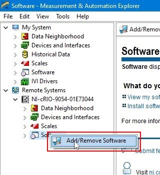
1. Open NI Max. Expand Remote Systems (1) > NI cRIO 90xx hardware (2).

2. Right Click on the “Software” and select “Add / Remove Software”
3. Enter the login credentials and click OK button.

4. The cRIO 90XX is already installed with CompactRIO 19.6 drivers. We need to access the cRIO from LabVIEW 2020. So we need to update the software in cRIO hardware.

5. Select the CompactRIO driver version matches with LabVIEW version (1) . Click Next (2) button to proceed further.

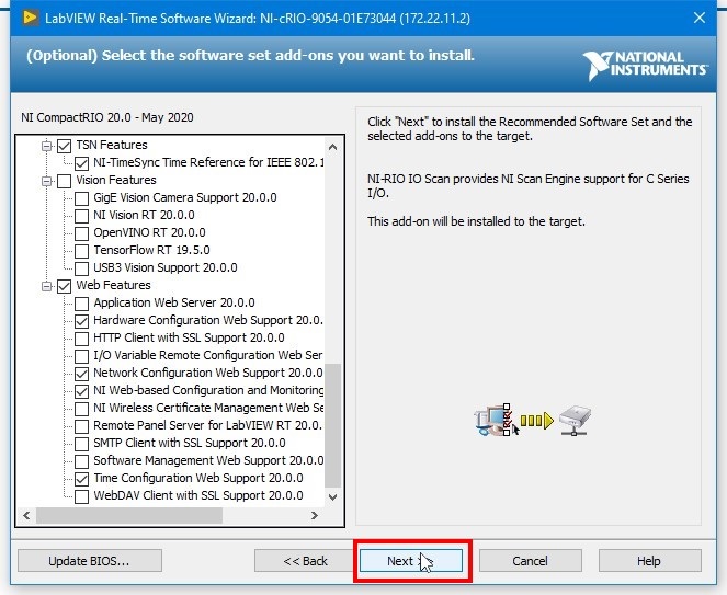
6. Select the required software addons to be installed in cRIO and click Next button.
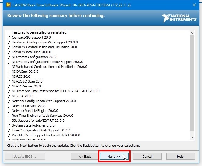
7. Review the software list and click Next button.
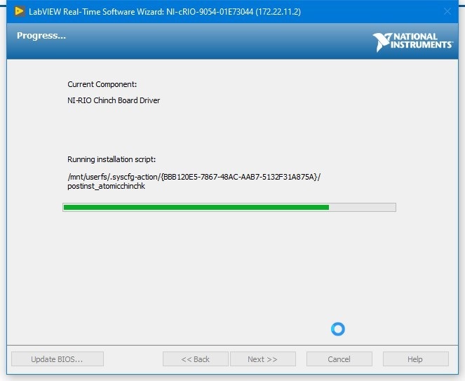
8. It will take few minutes to complete the installation.
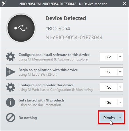
9. During the software installation, the device will restart multiple times. Click Dismiss button to close the window.
10. After completing the installation, Click the Finish button to close the window.

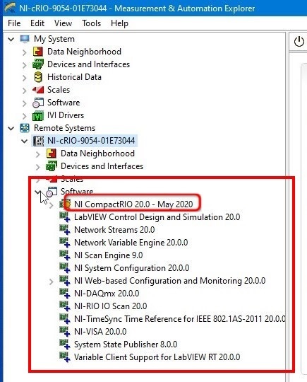
11. Expand NI cRIO 90xx > Software and confirm that preferred software version is installed in cRIO hardware. (In this example, we are upgrading from cRIO drivers 2019 to cRIO drivers 2020).
Note : Whenever we connect the cRIO to the host PC contains different version of LabVIEW software, we need to upgradae/downgrade the software installed on cRIO to match the host PC LabVIEW version.
Generally recommended list of software tools for the RIO hardware is given below.
1. LabVIEW RT Add-ons
(a) LabVIEW Control Design and Simulation
(b) NI System Configuration
(c) System State Publisher
2. Network I/O
(a) Network Streams
(b) Netowrk Variable Engine
(c) Variable Client Support for LabVIEW RT
3. NI Scan Engine
(a) NI-RIO IO Scnn
4. NI-DAQmx
5. Protocols and Buses
(a) NI-VISA
6. Web Features
(a) Hardware Configuration web support
(b) Network Configuration web support
(c) NI Web-Based Configuration and monitoring
(d) Remote panel server for LabVIEW RT
(e) Time Configuration web support.
Note: Its recommended to install only the required add-ons on the cRIO to leave the maximum free space in the disk.
1.2.4 Selecting program mode for c-series modules
CompactRIO with NI-DAQmx is the latest addition to the CompactRIO controller family. It brings two software experiences into one by combining the ease-of-use of NI-DAQmx and the low-level functionality of LabVIEW FPGA.
LabVIEW provides three programming modes for CompactRIO systems.
1. Real-time (NI-DAQmx) Mode
2. Real-time (I/O Variable) Mode
3. LabVIEW FPGA Interface Mode
User can configure the c-series modules programming mode in NI MAX.
1. Open NI MAX
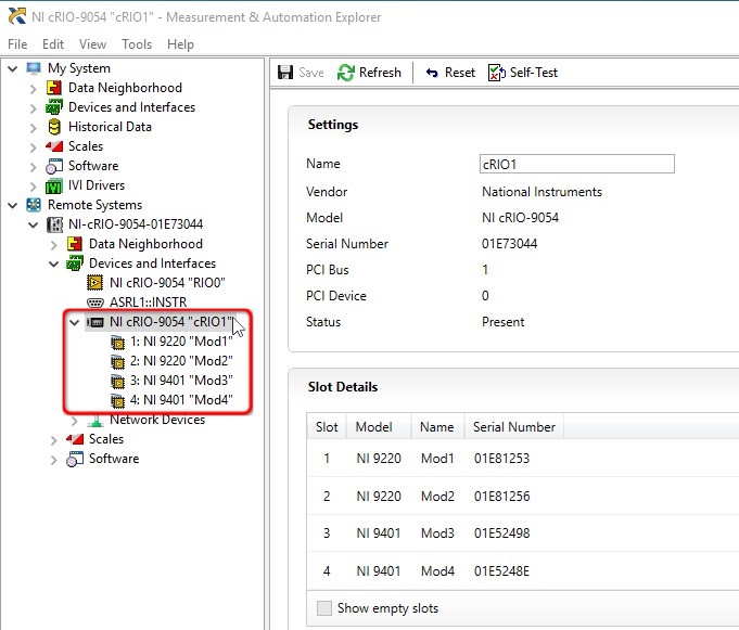
2. Expand the Remote Systems. Expand the NI-cRIO-90xx > Devices and Interfaces > NI cRIO-90xx “cRIO1”
3. The modules are configured as given below

(a) Slot 1: NI 9220: Real-time (NI-DAQmx) Mode
(b) Slot 2: NI 9220: Real-time (I/O Variable) Mode
(c) Slot 3: NI 9401: LabVIEW FPGA Mode
(d) Slot 4: NI 9401: LabVIEW FPGA Mode
4. Select the NI 9220 “Mod1” (1) in the left side panel. Click the Program Mode dropdown menu and select LabVIEW FPGA (2). Click the Save (3) button to save the configuration.
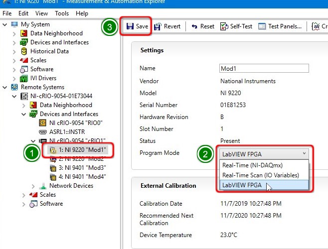
5. Now the NI 9220 “Mod1” is configured in LabVIEW FPGA Mode.

6. Select the NI 9220 “Mod2” (Slot 2) and configure it for LabVIEW FPGA Mode.
7. Now all the four modules are configured for LabVIEW FPGA Mode.
1.3 Configuring the sbRIO based hardware
When we use sbRIO, we need to add the I/O channels manually to the FPGA target.
1. Select File > Create Project to open the new project. Select Blank Project (1) and Click Finish Button (2)
![]()
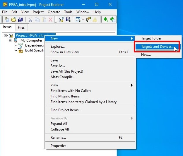
2. Right Click on the project title and select New > Targets and Devices
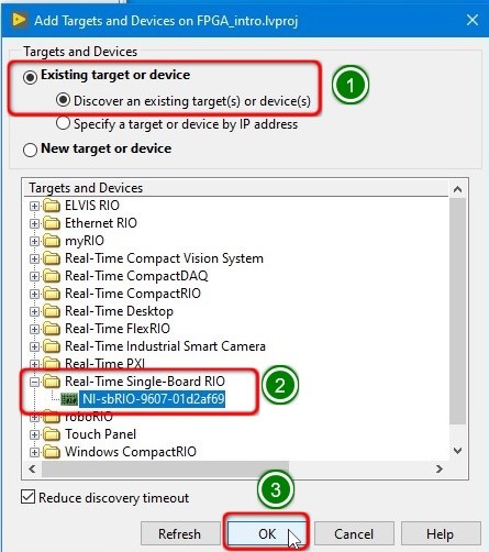
3. Select the Existing target or devices and Discover an existing target(s) or device(s) (1). Expand the Real-Time Single-Board RIO and select the sbRIO-9XXX hardware (2). Click OK button (3) to add the target to the project.
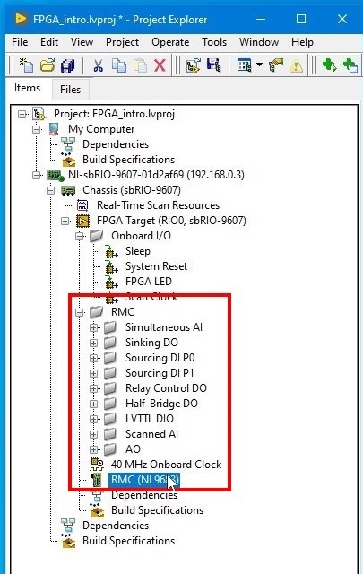
4. Right click on the FPGA Target > New > RIO Mezzanine card…

5. Click the RMC card Type drop down menu and select NI 9683 (1) and click OK button (2) to add the RMC card to the FPGA Target.

6. NI 9683 RMC is added to the FPGA target. Now we can access all the I/O channels available in the RMC card from FPGA target.
1.4 Recommended project architecture
When programming a RIO device (CompactRIO / sbRIO), the user will get three different target environments to run the program.
1. Host System
2. Real-Time (RT) Processor
3. Field-Programmable Gate Array (FPGA)
The host system provides the user with a Graphical User Interface (GUI) for monitoring the system’s state and setting operating parameters.
The RT Processor runs the main Real-Time program and is what allows the RIO to reliably execute programs with specific timing requirements.
The FPGA is a reprogrammable silicon chip and is at the centre of the embedded system. The FPGA connects the chassis I/O directly to the RT processor without going through a bus, which allows for very low control latency for system response compared to other controller architectures. FPGA speed and reliability are often used for applications using high-speed buffered I/O, fast control loops or custom signal filtering.
LabVIEW project may consist of multiple VI and they are expected to run on different environment like FPGA, RT processor or Host PC. Its good practise to save them in proper hierarchy.
1. Select File > Create Project.
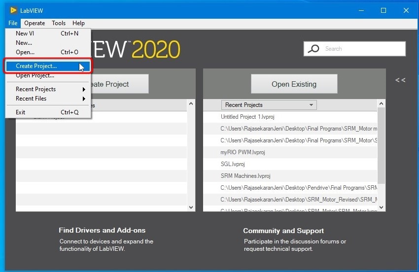
2. Select the Blank Project (1) and Click the Finish (2) button. Now Save the project. Its recommended to create a new folder to save all the files related to this project.
![]()
3. Right Click on the Project Name > New > Targets & Devices.

4. Select the Existing target or devices & Discover an existing target(s) or device(s)(1). Expand the Real-Time CompactRIO. It will search and display the “NI cRIO 9XXX”(2). Click OK button (3) to add the RIO hardware to the project.

5. Now the cRIO 90XX hardware is added into the project.

When we add the cRIO to the project, all the I/O modules are detected and added to the project automatically.
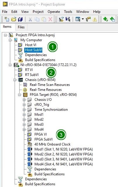
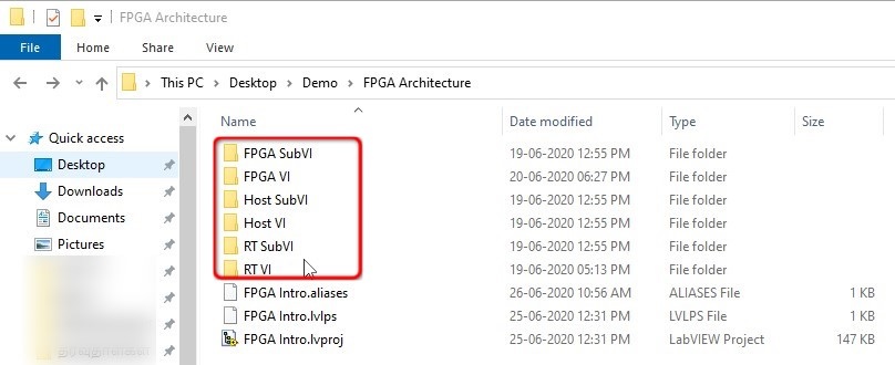
6. Its recommended to create Host VI, Host SubVI, RT VI, RT SubVI, FPGA VI, FPGA SubVI folders in the project root folder.
7. Right Click on the FPGA Target > Add > Folder (Auto-populating).
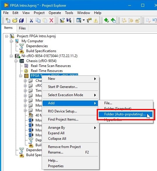
8. Select the FPGA VI folder (1) and Click Select Folder (2) button.
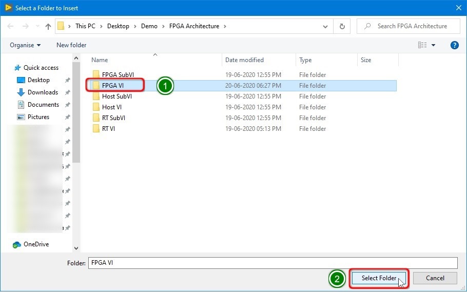
9. It will open the FPGA VI folder (1) and then click the Select Folder (2) button.

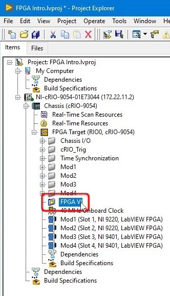
10. Now FPGA VI folder was added to the project. Repeat the same steps and add FPGA SubVI folder to the project.
11. Right Click on NI cRIO 90XX > Add > Folder (Auto-populating). Add RT VI and RT SubVI folders to the project.

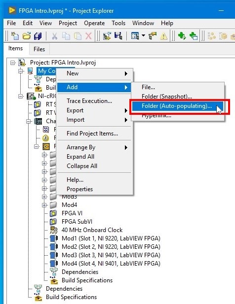
12. Right Click on the My Computer > Add > Folder (Auto-populating). Add Host VI and Host SubVI folder to the project.
13. Its recommended Project architecture and all the examples mentioned in the manual will follow same architecture. Host VI & Host SubVI folder contents will run the PC (1). RT VI & RT SubVI folder contents will run in the RT processor available in the RIO hardware (2). FPGA VI and FPGA SubVI folder contents will run in the FPGA processor available in the RIO hardware (3)